


Propeller Thrust Estimating
Question:
Hi. I have been looking at small electric outboard motors and note they are often rated for the THRUST they give.
I have 2 questions. Is there a way to convert that to horsepower, and is there a quick way of estimating the Total Resistance of a boat in order to estimate the possible speed based on that thrust ? Pedro-G, BR
.
Answer: Before throwing down some figures, I’d first like to clarify terms that are commonly used concerning propellers, as judging by discussions on boating forums, clarification is needed. And if I get off subject a little, excuse me as we don’t get to talk propellers very often, and the only short answer to your question is to go to the graphics I have included. Others may want to know a little more.
So first …. some terms, which I will elaborate on, to better understand their value and function.
Diameter is obvious .. .. and for slower boats, the larger the diameter the more efficient the propeller can be, as long as water can reach ‘the disc’ that the rotating propeller inscribes, and that the blade tips are not too close to the hull. But at high speeds, tip speeds, blade friction and resistance of the relatively large shaft brackets, all negate the initial advantage of a larger diameter and dictate that it be smaller. More later.
Pitch is the twist on the blade and is first defined by the geometric pitch … which is the distance the prop would advance (assuming zero slip) when turned one complete turn. Imagine, a slow turn in cheese .. or virtually a solid.
If we multiply that pitch (in ft) by the turns per min (RPM), we will get a theoretical advance in Ft per Minute, and the maximum boat speed can never quite reach this figure and is more commonly significantly less …. even 30-35% less for a heavy boat.
This difference is due to Slip .. a form of cavitation** due to the boat (or bollard) resistance being too high for the propeller to advance equivalent to the theoretical Geometric Pitch of ‘Pitch x Revs’. This Slip is typically at a maximum 100% when the boat is tied to a bollard, but can drop very low at the other extreme .. even down to only 2-3% for a high speed hydroplane that at speed is virtually out of the water with minimum resistance. Most boats are somewhere in between those extremes, with tugboats optimized to operate most efficiently at very low speeds.
So, if the propeller were able to turn in a solid, there would be zero slip … like a bolt turning in a matching nut. But in water, a propeller will always slip .. and the more ‘pushing’ work it has to do, the more slip, so when the boat is tied to a bollard or is very heavily loaded and restrained, its Slip is greatest.
We now come to the aspect in question … thrust
Thrust is the force of water coming from the propeller slipstream. It is greatest when there is maximum resistance .. which can be from either a very heavy resistant boat or one tied to a bollard - a dockside post. [Think of pushing a cardboard box against a wall.. The easier the box moves, the lower the applied thrust will be, but when the box hits the wall, your thrust will reach a maximum and the box will be crushed]. Zero thrust occurs when there is zero resistance to push against.
But there is another factor affecting propeller propulsion and that is the wake.
Wake is the water that the boat itself pulls along with it, partly due to its friction but mostly due to its shape. This wake is very high for boats that are fat amidships but then reduce quickly in section. Such a form ‘sucks’ along water at the stern, often just where the propeller is located, with the result that the propeller is now thrusting its slipstream against water that is now moving in the same direction as the boat. This is effectively like having additional slip, as the propeller now needs more pitch just to compensate for this reduced wall of water resistance that a free ‘open water’ propeller would be working in.
As this might initially be hard to grasp, think of this. Compared to a boat moving through still water, having a wake is like a boat facing a current. Clearly, a propeller would need some pitch to hold a boat in position against such a current, so to compensate for the effect of wake, one needs to add extra pitch. Another approach is to consider this 'wake water' as weight and displacement, quasi-attached and dragged along by the boat. Again, this would require more pitch to give the increased thrust needed for the added weight.
You may now understand why this wake value is added to the real 'propeller' slip to create a total 'apparent slip' as both dictate more pitch, but also why planing motorboats can be more efficient, as their wake once planing, often drops to around 5% of the boat speed, freeing up more pitch to give extra speed, whereas for a boat with a heavy-middle-body boat that drags a lot of water behind it, the wake may be 25% … or 5 times more in this example ! If indeed, the propeller has to work in that suction area behind a full middle body, high speeds are just not possible. By contrast, the outboard on a fast planing boat, is not only working in clean open water, but the boat is also not dragging much wake water with it either.
So when we think of the rapidly climbing resistance of a displacement hull, the rate of added resistance when at planing speed makes a significant drop and while it still increases with speed, the rate of increase is significantly lower, provided the hull shape is modified to support planing .
** a note re the above use of the word ‘cavitation’.
While true prop cavitation is normally considered as ‘the formation of small cavities of partial vacuum due to locally reduced pressure’, the lack of full pressure against the blade that allows ‘slip’ when the boat is tied to a bollard, may loosely be dubbed cavitation as well.
As Cavitation can be caused by excessive prop speed (or even diameter), insufficient blade area, or operating in an area of lowered pressure (eg: too close to the hull surface or behind a bulky fixed structure), the opposite of these factors will reduce it. Cavitation typically starts at the blade tip and as conditions worsen, progressively covers the whole back of the blade. The blade not only loses lift but the negative suction bubbles ‘pop’ against the blade and cause quite severe blade erosion with increasing speed.
So what does one do to get more power to thrust a boat much faster, yet avoid the erosion? That’s’ where the ‘super-cavitating’ propellers kick in. These accept and even encourage air on the blade backs. So instead of getting thrust from both ’face pressure’ and ‘back lift’, the super-cavitating prop concentrates only on face pressure. While this initially lowers efficiency perhaps to under 50%, the extra prop speed that is now available actually starts to raise the efficiency again and it can climb back up, even to 70%. The blades for super-cavitating props are of a very different section though, now having a very fine entrance with a wedge shape blade and a blunt rear edge .. so can look something like this. 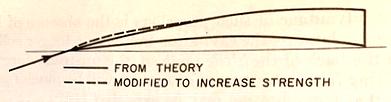 Although the leading edge needs to be very fine, in practice this has to be compromised, or the blade is not strong enough.
[Typically such props run at speeds in the 1000-3000 rpm range]
Although there are many variables to consider, I always find it interesting to have 'ballpark values' in mind. (When working with a 'slide-rule' before computers existed, this was essential as we had to decide where the decimal point was ;) So here's one. Cavitation typically starts to become an issue when blade loading much exceeds 10 psi but most regular props operate comfortably at about 1/2 that .. 4-5 psi. So working backwards, an operating thrust can be crudely estimated for your prop from its total blade area x 5 (in sq inches and lbs). This will need to slightly exceed your boats resistance at your design speed or operating condition.
.
Let’s now look at the specific question … the value of: Thrust compared to Shaft HP.
======================================================
In simple terms, Thrust = Prop.HP / Vel at prop, so higher the velocity, lower the thrust.
Imagine it like pushing a stalled car …. once it’s rolling, the effort drops. Maximum propeller thrust is theoretically produced only when the boat is prevented from moving by attaching it to a bollard (dock mounted mooring pipe), that’s why NA’s call it The Bollard Pull. (Such a pull is tested with all full size boats that need high thrust at low or zero speed .. such as Tugs). There is then also maximum 100% Slip as the boat is prevented from moving forward. (Like pushing your stalled car until your feet slip … that’s the most you can thrust in those conditions … same for a prop in water)
Once the boat is free, a couple of major things happen. The slip gets less as the prop starts to move forward and better 'grip' the water, plus, some water is now pulled along with the boat … a small amount (2-3%) with a planing boat but could be 20-35% with a displacement hull. This is called the WAKE. This partly annuls the slipstream, so, as explained above, works like additional slip to the prop, so the Pitch needs to be further increased to maintain enough thrust to push forward and create speed, but once the effective thrust equals the boats resistance, no more speed is available. As this thrust will be much lower than the maximum Bollard Pull thrust and varying with speed, slip and boat resistance, only the maximum thrust at near ZERO speed is typically quoted by O/B engine suppliers and for this, a propeller efficiency has to be assumed or estimated.
When tied to a bollard for maximum thrust, this can be Calculated by the Prop developed Slipstream, the Prop Efficiency and the Horsepower. The theoretical maximum slipstream speed is a product of Pitch x Revs.
Lets work an example: Pitch (20 inches) x 600 (rpm) = 12000 inch/min or 1000ft/min or 60,000 ft/hour. Dividing this by 6080 gives 9.87 knots.
Thrust = SHP x Effy / Speed. But to reach common units, we need to convert SHP into ft.lbs and Knots into ft/min. So to convert, we need to multiply by '33000 x 60/6080' .. or 325.6.
So Maximum (Bollard) Thrust = 325.6 x Effy x SHP
Slipstream (Kts)
So the final accuracy all comes down to ‘our estimate of the propulsive efficiency’
If we know the SHP is 40 and ‘assume’ the efficiency as 0.7, then the Thrust would be: (325.6 x 0.7 x 40) / 9.87, giving the calculated Max thrust as 924 lbs
So for this case, the lbs-thrust per hp = 23.1, placing it in the typical range of between 20 and 30.
[In fact, the power should be the HP developed at the reduced RPM caused by being tied up to a bollard, but then should be used with the slipstream speed also reduced due to some inevitable slip. But if both were reduced say by 15%, the result would be the same (as one is on the top line and the other on the bottom of the equation )].
Because the only truly accurate way of finding the Max Thrust of any particular Prop / Slip / Boat combination is to do a test using a Thrust Meter or Load Cell, we have to live with approx. associations of Shp to Thrust, based on tests that have been done.
Here is a graph created from previous test results. Because of all the variables, this cannot be accurate for all cases, but +/- 15% it’s generally ok. I have seen higher figures for low HP tests, but I suspect they come from proportionally higher prop efficiencies.
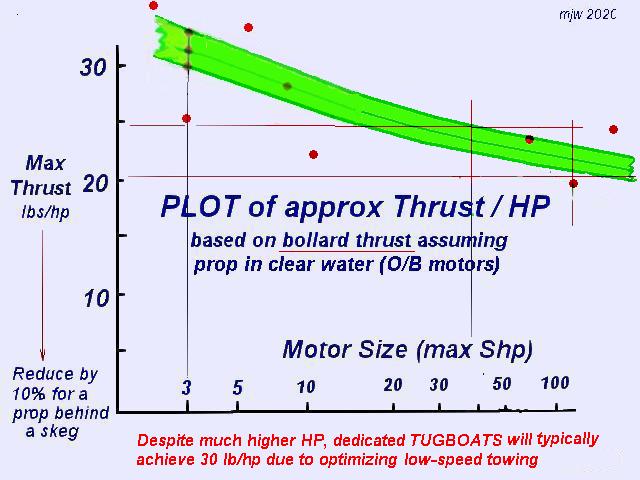
At zero boat speed, propeller slip will be high if testing a high pitched prop with high revolutions, so for a TUG operating at low speeds and needing maximum bollard pull, the pitch (and therefore its slip) will be kept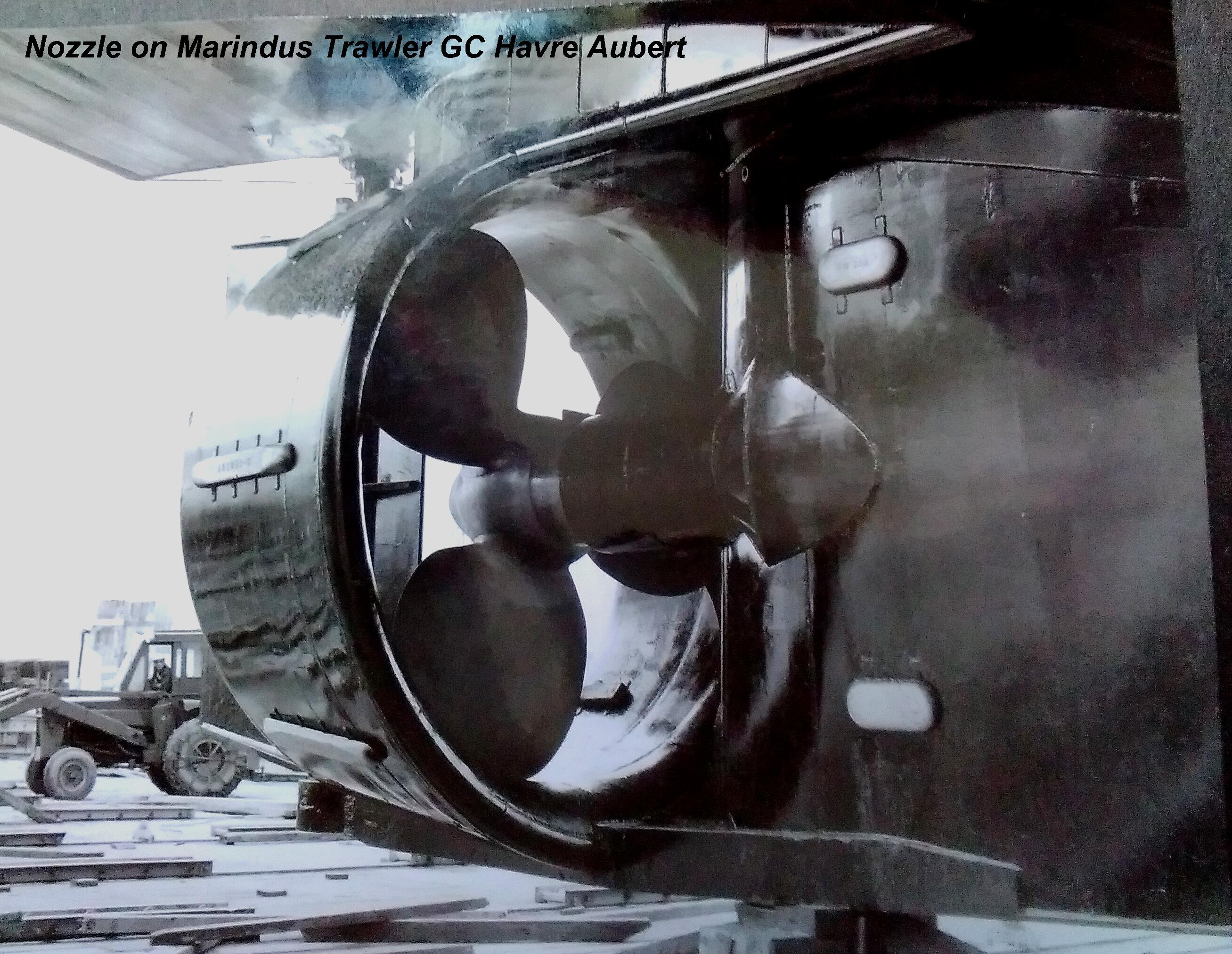 as low as practical but given enough pitch to absorb maximum available horsepower. A typical tug prop might have a pitch of only 60% the diameter, whereas a fast motor boat would typically have a pitch significantly higher than the diameter, say 130%. Today, most tugs have propellers placed inside a Kort Nozzle, a solid ring with an aerodynamic shape that feeds water flow from a larger diam, but narrows down for a smaller prop that operates now in a venturi. Experience shows this can add 35-40% to the forward thrust. Astern thrust is reduced though. Here is one I once fitted on a trawler.
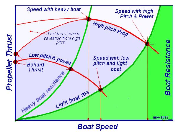
Props for slow-trolling fishing motors are designed rather like a tug, so thrust values given are valid for near zero speed. But as the boat moves quicker, boat resistance starts to climb while the prop thrust falls and when they are equal, the boat will go no faster (see diagram below). Prop pitch can be increased a little for more speed but as power is limited one can soon overload the motor. Adding blade efficiency by using less blades of greater diameter will help, and we see this with props used by Torqeedo and others. This only works with lightly loaded props for low speeds and when there are no significant restrictions on prop diameter.
The graph below shows two different cases. The lower curve in the blue area is typical of a light boat with a low pitched prop that will give high thrust at low speed. Trolling motors fit this description. The upper curve shows that more representative of a fast boat with a large pitch. The pitch will be too much for efficiency at low speed as the prop will inevitably cavitate until the boat picks up speed, so initial thrust will be lost. Although the thrust will still fall off at a higher speed, it will be sufficient to drive a much faster boat, providing the boat is fairly light and has a planing shape. (This graph shows the 'effective propeller thrust' as the inevitable SLIP is factored in).
So if the boat design speed is high, higher prop pitch will be needed as well as more shaft horsepower. For high speed planing hulls, large props that add efficiency when turned slow, no longer work as associated friction from their blade area and their supporting brackets gets too high, plus blade-tip speeds can be too high also. So props are kept smaller diameter but need much higher pitch. They are now turning perhaps 10 times faster, so a more typical prop for this case would be a prop with a pitch 30-40% more than its diameter. While it may seem logical to get the pitch that uses all the available horsepower at the maximum speed, for most practical use, somewhat less pitch is advised so that the motor/boat combination has a reserve against the higher boat resistance that occurs in rough water, but this lowered pitch also allows the prop to work better at lower boat speed so improving low speed manoeuvring. As with most things in any variable environment, compromises must be made … in this case, the top end speed will drop … perhaps 10%.
If there is enough blade-tip clearance with the boat and the required thrust does not overload the blade area, then a 2-blade prop is the most efficient, as there is more undisturbed water between each blade. But if high thrust is required, more blades will be required, as having too high a unit-thrust (lbs.sqin etc) on a blade will invite cavitation and can also over-stress the blade root physically. That’s when one uses a 3 or 4 blade prop.
Prop efficiency with more blades, (when measured in open water) is theoretically lower, but the other factors mentioned above more than offset this. [On large ships, there is often not enough blade-tip space to get the needed area, so even 5 or 6 blades are seen, when prop designers have to get creative with ways to even overlap the blade tips]. Designing the best props has now become so complex that it’s no longer a side line for a naval architect as it commonly was in the 1950’s and earlier. Now it’s a full time study and specialty, based on controlled tank tests from which design software is often created. Mind you, I personally still remain skeptical of 'software that offers the ultimate solution' as far too many ‘pure programmers’ have got into ‘this art’ without having the tech knowledge to know all the variables and compromises needed. Ideally, the 'software design' needs to be first done by the qualified specialist, and only then get programmers involved to execute the design.
A personal note on this:
I just recently was made aware of a company working on large powder mixers. They were offered software to figure out the flow but the research engineer responsible found the predictions out of line of what he expected. So as they were to build a number of these mixers, they built a large scale model of clear plastic so that with dyes, they could actually ‘see’ what was going on .. and the software predictions indeed proved woefully inaccurate. Good for that research engineer to not accept software without a few good checks on the inputs used and the conditions assumed. If the base data is all mathematical formula based on sound science, then computer programs are great. Boat hull hydrostatics are a good example of that. But for many other issues where there are many unknowns, it's very risky to work with software that's created with assumptions built in (and many do) ,,,, assumptions that are no longer apparent to the user. Actually, Excel spreadsheets will do much of the calculation work and there, the formula used are easy to access, check and confirm, to see IF they apply to the task in hand.
Even good web sources can seem contradictory.
Here’s a recent one that confirms my own learning from the 50's that says … “Less blades are more efficient”. But then, a noted MIT engineer writes that; “5 blades are more efficient” !!
So who is right ?
The fact is, they could BOTH be right, but for different cases.
Less blades require bigger diameters and often the space is not there. Often props have to operate behind stern frames and supporting struts etc. and as the prop rotates, the blade at the top can have less pressure - so greater cavitation as it passes…. adding vibration as it rotates (especially noticeable on large 2 and 3 blade props). A 5-blade prop is affected less in this case and can give the required blade area with a smaller diameter, so increasing tip clearance. [Such 5 blade props now sometimes have a cup of the rear edge of each blade to reduce negative flow to the blade following it]..
These situations typically do NOT apply to an outboard motor that is operating clear of the ships hull, so many different types of props can be used there without the problems associated with fixed ship installations. In fact I read recently that many large popular O/B’s can now each fit up to 100 different props to suit different boat applications .. wow ! But certainly for low power with good tip clearance, a 2 blade will be more efficient, so for human-propelled prop at the other end of the scale, this would make sense.
=======================================================================================
A way of Rough Estimating the Resistance of various types of boats is the subject of an article posted Jan 2024
Mike ... posted Dec 2023
"New articles, comments and references will be added periodically as new questions are answered and other info comes in relative to this subject, so you're invited to revisit and participate." —webmaster
"See the Copyright Information & Legal Disclaimer page for copyright info and use of any part of this text or article"