


How to bend a wide Mainsheet Track
The W17, like the W22, uses a wide mainsheet track that offers the potential for excellent mainsail control, by playing the traveler instead of first letting go the mainsheet. This keeps the sail acting as an efficient wing instead of permitting a large bag at the top when only the mainsheet is released—something that not only lowers its efficiency but makes it hard to re-sheet with sufficient leech tension to reclaim the preferred wing form.
Although wide, curved mainsheet tracks are available from some marine hardware suppliers, the delivery cost of this curved piece can be very high. When the risk of shipping damage is factored in, it's not surprising that some suppliers only ship straight lengths of long track.
So the question becomes: how do we bend this long, stiff section into a nice even curve that a traveler car will run over smoothly? One solution is to use a pipe section of adequate size instead of a dedicated section. Some W17 builders have already done this and there are professional pipe benders that can handle this job effectively.
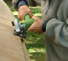
But let's say we want to do this ourselves—and even use the extruded alloy section that a number of marine equipment manufacturers produce, together with matching cars on rollers.
The first thing we need is a bending jig. This is something that can be built from scrap wood that most people have laying around.
Here's the general idea. You need 2 pivoting guides that closely fit the track width and have a bearing surface for the track side.
Then there will be a central, curved ram die, that will also fit the track width and the bearing surface on the inner side. This ram will have a recess in the underside of about 35 mm dia. to take the round, adjustable head of a small hydraulic jack. Anything from 2–5 ton capacity will work fine.

Here's the jig and the dimensions that I used to bend my own track. Each track will need a slight adjustment for the shape of the guides. In my case the track came from Barton Marine. I chose this one as it's closer to a square than others, and therefore easier to control possible twist. But even here, the top flange was slightly thicker than the bottom flange, so in order to offset any slight twist that would result from a straight push, I needed to create a pushing ram with more curve on that stiffer side, so that after the inevitable material 'spring-back', the section would lay flat and horizontal. In my case, I increased the camber within the central ram die on one side, from the 9 mm shown to 10.5 mm on the top flange side and that produced a nice curved track without twist.
I constructed this jig from scrap material, and the dimensions should suit most track bending needs.
The pivoting side blocks will have dimensions for the track somewhat similar to the central die (though just in wood), so that they support the upper side flange evenly.
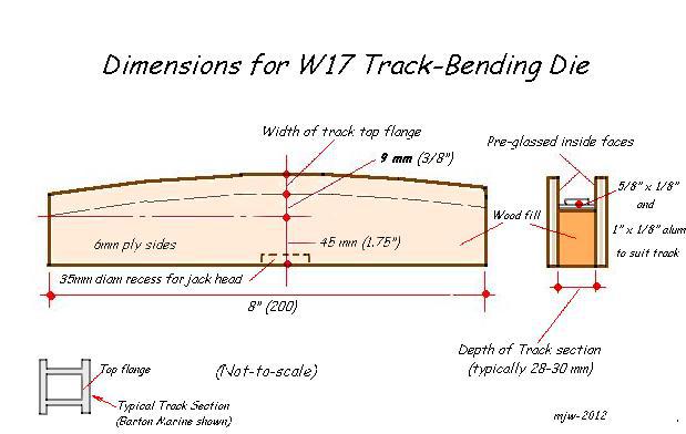
Here also, are the dimensions of the central die. Although specifically made for the Barton Marine track that I used, it can be readily adapted for most track sections of similar strength and, typically, these tracks will carry mainsheet loads of up to 300 lbs over free spans of 700 mm.
The main jig also has a wood block stopper above the track, suspended from a ½" diameter threaded bar, so that raising of the hydraulic ram can be limited. If my memory holds good, I believe I initially set the block at about 15 mm above the track and die.
The final camber (over the 200 mm width of the pushing die) is only about 2 mm, but you will have to push considerably past that, to allow for the material spring back.
Initially, I suggest you mark the track every 100 mm, with another mark of different color in between at 50 mm. These 100 mm marks should each in turn be centered over the pushing ram, and then pump up the ram and track, against the stopper. Then release the pressure, slide the track through 100 mm and repeat the operation.
For the W17, you are looking for 300 mm total camber over the full 2.20 m track chord, so once you have made one pass, check to see how it's working out. If it's still not enough, pass the section through again, but this time, stop at the 50 mm marks to further even-out the bend. Should you find you have slightly OVER-bent the section, you can reverse the track—and give a little ram pressure at the original 100 mm markings. The secret to getting a nice even curve is to go slowly through the whole track length and not over bend at any one spot—and then check the overall camber before passing it through again.

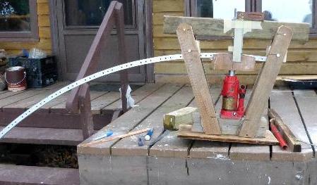
This picture shows the stopper doing its job and also how the pivoting side blocks support the track.

Finally, this photo shows the track being 'trial-fitted' to check that the 300 mm is about correct. It's not critical to be more exact than say +/-15 mm.
Mounting the Track
For mounting, I chose to use aluminum flat bar as it was easy to locate and required no welding. I sandwiched it between pieces of hardwood in order to bend it and with the flatbar in a vice lined with plywood, the wood gave me enough extended leverage—and you can always add a large vice grip over the wood to add even more levering power. Check often as, again, there's a fair amount of spring-back. Here are the final pieces installed.


The main hull mount will fit around the gunwale and bolt through the ply pad you already added for the beam. The outer mount will require that epoxy cores are created for the bolts and/or large lag screws (5⁄16" - 8 mm recommended).
These can be created by filling ½" diam holes with thickened epoxy and perhaps some added 4mm lengths of chopped glass. Cut a strip of scrap ply the same as the aluminum flat bar you are using and drill holes in it at the same location. Then oil the fastenings you are using and with a piece of wax paper against the beam, gently push the fastenings into the epoxy and tape in place. Once hard, crack open the fastenings with a wrench and remove. Clean up the surface and install the aluminum bracket with fresh epoxy in the holes.
The track may also be mounted using 5⁄16" (8 mm) diam threaded S/S rods, welded to flat 2mm thick plates that are bolted in place, but I think the flat bar solution adds more lateral stability. A photo of the first red W17 shows this installation at the very bottom of this Waters-Edge page 4/
mike–2012
Read more Construction Tips & Techniques.
"New articles, comments and references will be added periodically as new questions are answered and other info comes in relative to this subject, so you're invited to revisit and participate." —webmaster
"See the Copyright Information & Legal Disclaimer page for copyright info and use of ANY part of this text or article"