


Building the W17 Main Hull — Part 4: Beams & Cockpit
Part 3 finished with the decks being added, so the final step is to mount the main cross beams, cockpit storage boxes and sprit housing.

The installation of the hinges and latches for the main to outer wing-beams, must first be complete. Note that it's important that the hinge pins for the upper hinges are installed exactly at 90° to the beams, in order that they permit folding without being stressed or damaged.
In order for the hinge pins to line up longitudinally, the beam tops must also be in perfect alignment and the best way to assure this, is to clamp on 1 or 2 straight edges to the top of the beams. You will find that you need a small shim of about 2.5mm under the rear edge of the forward beam and a smaller (1.5mm) shim under the forward edge of the aft beam. The shim itself only needs to be about 10-15mm wide, as the balance of area can be filled with a lightweight filler.
Once you have the shims fitted, I suggest you pre-bond them in position to the deck so that they do not slide around as you install the beams.
The beams then need to be drilled for the 8mm diameter retaining coachbolts. I suggest to drill these at 290mm off the centerline for the forward one and 280mm off centerline for the aft one. This still provides ample access for tightening the nyloc nuts below deck (installed with large S/S fender washers).
Before bonding these beams, I found it easier to prefit the cockpit seat ply each side.
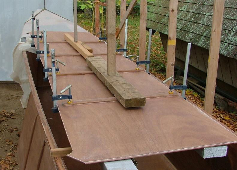
These panels first need sheathing on their underside and also have 4 hardwood stiffeners bonded to them – with their underside surfaces well rounded.. Inboard ends can be tapered to about 9mm depth and notched 10mm into the gunwale. The outboard ends can be ground down to only about 1-2mm. One or two straight edges of 8ft length, placed athwart-ships over the seat ply, will hold them up in place while they are fitted and bonded to the main-hull gunwales.
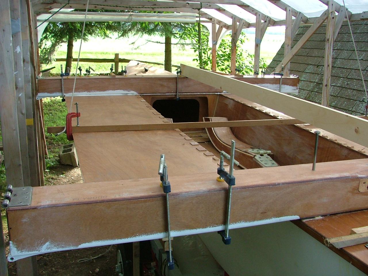
The main transverse beams can then be bonded over. Just in case the gunwale heights are 1–2 mm off port to starboard, it's also important to stand at the rear of the boat and look across the two beams in position, and see if they are exactly parallel to each other. If not, you'll need to add a small shim under one side of one of them to correct that. Measuring up from the hull bottom and comparing sides, should help establish which is the low point. The centerline of each beam needs to be clearly marked and then the beams set about flush with the cockpit edge of the deck ply – and exactly at 90° to the boat centerline. (see manual for way to check this). Once in position and shimmed to have the tops in line, drill through for the bolt holes. Then bond the forward beam in place, lightly snug down the bolts and then measure to place the aft beam exactly parallel. Again, with beam tops in line, bond the aft beam in similar fashion. Do not overtighten the bolts—just snug to squeeze out excess filler.
The final main-hull woodwork, is for the cockpit seats and lockers. First fit and bond on a small 20 x 10 strip to the top edge of the outer ply verticals.

The main hull has about 10mm of sheer between the beams, so you have some options for the outer box verticals. You can either:
- fit them with a similar sheer on the lower edge, or
- install them straight on the underside and pull up the outer edge of the seat ply to fit (this was my choice).
Either way, the lower edge of the inner (sloped) cockpit box face will require to be slightly deeper in the center than at the ends.
Once the outer verticals are fitted, lay in a good, strong fillet of high strength epoxy and after sanding, lay a 50mm glass cloth over this 90 deg. joint inside, so that future trampoline straps will have something solid to bolt to.
Then fit the two small partition bulkheads about 690mm from each of the beams.
TIP: I recommend to pre-cut a 2.5" (63) diameter hole in each of these partitions (slightly towards the sloped face), so that items like a tiller extension, can be stored more easily. You will also need to plan complete drainage, as these open lockers will collect at least some rainfall. You can either drain them internally to the aft end or you can vertically drain each compartment individually. Either way, drain holes should be at least 15mm diameter and drilled both sides of the space, in case the boat is leaning either to port or to starboard, say on land. (If water is found to drive up these holes from outside, it's easy to later bond on a small deflector of plastic or rubber to the underside, to create one-way drainage).
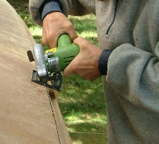
Once the partitions are in place, fit the sloping inner sides after having first cut and sanded the long access holes (I made mine 300–350 x 65).
TIP: To add a little extra strength to the small wood strip under the upper edge in way of the holes, I first laid on two strips of glass UNI tow. We know these boxes will be walked on after all!. Also, if your strips tend to not be straight, temporarily clamp on a straight 20 x 25 batten just a little shorter than the cockpit, while the small upper corner batten is bonded in place, as this will help to keep things in line.
Once cured, complete all the seams by laying in a fillet of thickened epoxy. In order to well attach the underside ply to the sloped face, it is advisable to added a few pieces of tape to the corner—but place these INSIDE the box so that the exterior stays clean. Then sand all the surfaces and give the interior 2 coats of clear epoxy before finishing with 2 coats of paint (white polyurethane suggested).
TIP: Before adding the box tops, the underside of this ply should be reinforced – either with full glass sheathing or with some athwartship strips of 50mm tape, spaced about 200 mm apart (the lighter solution ;-) This will add measurably to its capacity to be walked on.
Then overcoat with 2 coats of clear epoxy.
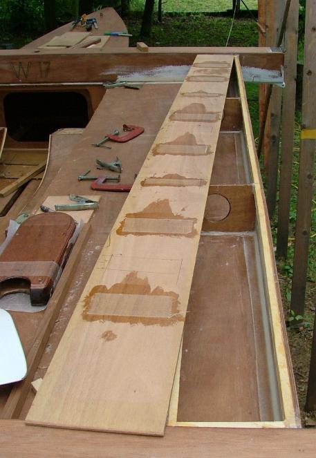
With the surface all ground and planed down flat and smooth – bond on the tops.
TIP: Again, using a long straight strip under your clamps will assure that the top stays flat while bonding.
Once cured, round off all corners to about 5–6 mm radius and after sanding, apply a sealing coat of epoxy. I suggest to add a 50mm FG tape to the edge of the main cockpit seats, as this corner will likely see lots of sandy shoes! Then sand and apply a 2nd coat of clear epoxy in preparation for 2 final coats of paint. You will now start to appreciate the size and comfort of this cockpit—all 50 sq‑ft (4.6 m²) of it.

One remaining thing to do, will be to mount the housing for the removable bowsprit. Make sure you've first wrapped a 9oz (300 gms) cloth around this box (at least a 50mm tape at each end), so that it can resist the strong side force. With the sprit installed in the housing, line up the forward end with the centerlines of the two beams and then drill the four holes down through the deck. The forward holes will pick up the gunwale and the after one, the cross stiffener of the small bulkhead for the forestay. Four flat-head brass screws of 60-65mm will do this. Then sand and bond in place with thickened epoxy, leaving a 4-5mm fillet all around.
Other than the forward beam faring and any extra hatchways you've chosen to add, the main hull should now be complete as far as woodwork is concerned.
See Main Hull — Part 1: Construction
See Main Hull — Part 2: Painting
See Main Hull — Part 3: Interior
Read more Construction Tips & Techniques.
"New articles, co mments and references will be added periodically as new questions are answered and other info comes in relative to this subject, so you're invited to revisit and participate." —webmaster
"See the Copyright Information & Legal Disclaimer page for copyright info and use of ANY part of this text or article"