


Some Basics on Foam Core Construction
Since the beginning of 2024, I have received several requests to ask if the W17 trimaran can be built in foam core. One good reason for this is that, the once considerable price difference with sheathed plywood is now getting less, particularly in areas where plywood has to be shipped in. Not only is the Marine Plywood itself getting more expensive, but it’s relatively heavy, so shipping cost has soared since Covid-19 spread around the globe. Shipping foam sheets is a LOT less expensive, so in some areas of the world, the net difference between a sheathed plywood boat and one of foam core is now (04/25) only about 15%, so more attractive to new builders than it ever was.
While foam cored boats are generally not as ultimately rugged as plywood boats, they certainly can be built lighter … typically somewhere between 15-35% lighter, depending on the details. Less weight clearly has implications for added performance, although a boat can be built
[ A later article will delve into the actual building of a W17 using foam cores ].
[But on the flip side, marine plywood is STILL a great material for a boat and for many, it makes for a more enjoyable building experience, with a material that is renewable with minimal pollution. It just needs to be kept dry and repeatedly well ventilated .. then it has proven to last over 50 years !). Building in plywood down to weight means choosing a lightweight but quality product, along with great care to minimize the sheathing weight, as poor control and overuse of epoxy can even double the plywood weight].
Some BASICS on FOAM CORE Panels
When designing or constructing a boat using skins + core, it’s important to understand how the various thicknesses relate to each other, so here are some basics to consider.
Before ‘tweaking’ for specific local needs, a basic core construction should have equal skins so that the neutral axis is centralized and then have skins thick enough to support the higher surface stresses in tension and compression, as well as having a basic resistance to surface puncturing. If too thin, the skins will buckle or pull apart. If too thick, the paneling will be too heavy & costly, so not justify its use.
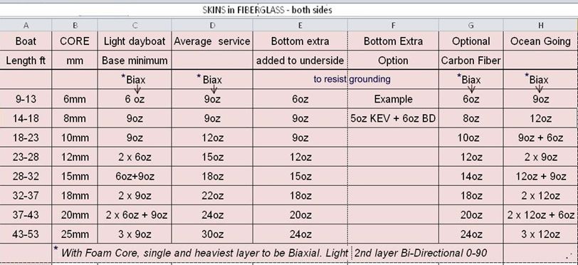
From my experience with test panels, here are some guidelines for minimum fabric skin weights, which are related to the core thickness.
It works out nicely that the minimum skin weight (in ozs per unit area) numerically closely matches the core thickness in mm, especially for carbon fiber, or as a basic minimum for FG. See the table below.
Note that these are MINIMUM thicknesses that apply with semi rigid core such as Corecell-80 (5lb) and for a boat looking for minimum weight that is not ‘ocean going’.
If the core is PVC, about 10% should be added to these minimum fabric weights for a new minimum.
Using multiple layers rather than one heavy cloth can improve penetration resistance.
But as this simple relationship first needs a suitable Core thickness, that should also be in proportion to the panel size, which in turn is typically in proportion to the boat length. Also, while the basic core figure works fine when there is some curvature to the panel, flat panels can use core panels up to 35% thicker unless they are stiffened with extra stringers etc. so each case will need some common-sense applied.
For the basic core thickness, an easy relationship exists; by taking our ‘Boat Size Factor,’ as ‘Half the main hull length in Feet’. With that in mind, a suitable nominal core thickness in mm, typically matches half the boat length in feet. 8mm for a 16 footer or 12mm for a 24 footer. (Columns A, B)
NOTE: The 'Boat Length' in table refers to a relatively long slim hull, Lwl/bwl > 6 (tri, cat, kayak etc)
We can adjust this up or down say +/- 15% to suit whatever is available and then, if we have chosen to use the thinner core, add an internal frame or stringer to compensate in way of the larger unsupported panels. Available fabric weights vary around the globe, so be flexible and use what is closest, compensating in logical ways if slightly lighter.
It’s quite common to also add a cored stringer in way of any exterior side potentially exposed to a collision – like the forward outboard side of an ama etc. A wood core will be stronger and more resilient to shock than one of foam. The latter will leave all the loads to be taken in the glass or CF shell, so be sure there is enough
Generally a main hull is well protected except for a bow area or for grounding (see below on this).
The minimum glass fabric weights also numerically follow the ‘Boat Size Factor’ but they are the minimum. What weave is required will depend on the core. With a foam core, the main fabric should be biaxial but a smaller percentage of the total fabric weight can beneficially be a 0-90 B.D (Bi-Directional) fabric that will add stability to the biaxial for lengthwise hull bending loads as well as for hoop stresses. With bonded strip cedar, the wood gives plenty of longitudinal strength but needs unidirectional cloth around its girth both inside and out, often with a light B.D boat cloth over the outside for added surface protection.
Using Carbon Fiber
If it is desired to go for minimum weight, then carbon fibers should be considered. While we may occasionally see suggestions to “use carbon fibers as low as 50% of the glass weights – to show significant weight savings”, this can be misleading and I will submit my reasons.
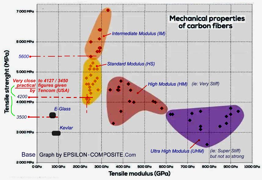
First it’s VERY important to be all “talking the same language” as far as carbon fiber strengths. You will find an extreme variation of relative strengths quoted on the Internet, partly because of this failure in ‘same language’ issue. There is a great range of CF material now available and you can best see this on this fine graph by Epsilon that I show below: Here we can see a range of 4000-7000 MPa in Tensile Strength and from 230 to 930 (!) GPa in Modulus. (Some non engineering users may even mix these two up, so for clarity, see the note below in italics:)
The other potentially confusing aspect is that the Properties stated (and given in graph below), are only for the carbon fiber itself and NOT for the final laminate that we create. The latter inevitably includes the resin matrix that is much weaker. But carbon fiber alone is not structural by itself, so ultimately, its the strength and performance of the final laminate that is important. While we will get to that later, its worth noting the obvious; that the strength of the carbon fiber in tension, depends less on the resin around it, than if the carbon fiber is working under compression. ie: a strand of carbon fiber tied to a finger of each hand, will effectively prevent you spreading your hands apart, but will do ZERO to prevent you from clapping your hands together ;)
“Modulus” is short for Modulus of Elasticity which is basically the Rigidity or Stiffness of the material .. which is very different to its Tensile Strength. In my humble opinion, neither ‘very high’ Modulus nor ‘very high’ Strength is a good material for boats as it has almost no flexibility to accept surprise overloads and therefore, one cannot afford to build taking advantage of the theoretical higher tensile strength. Also, it’s almost impossible for the unskilled eye to tell the physical difference in the materials so it’s only safe to assume that the carbon fiber you are buying is one of the weaker ones and therefore, one should design for the lower, safer value. And High Modulus is not good on any structure subject to shock loads as it’s too brittle. Sure, if you are building a foil for a racing AC75, that’s another story, but for hull shells, the lowest Modulus carbon material is actually often the most suitable. Tests have also shown that lower Modulus carbon fibers have a higher strength in compression than HM fibers, so that may factor in to your need. (More on this in a follow-up article)
This pins down the ‘useable practical values’ for carbon as being much lower than some figures you may see on the Internet, so I will try to explain why the majority should not use them. I have indicated ‘the safe values’ on this graph for Tensile Strength as 3500 MPa for E-Glass and 4200 MPa for Standard Modulus Carbon fiber. Even with a relatively low Modulus of 230 GPa, carbon has still almost 3 times the stiffness of E-Glass, so only very rarely do we want more. So instead of running off with the idea that carbon fiber is 3 times stronger than E-glass … check out these more ‘practical values’. The standard stuff most of us buy may really only be 20% stronger by volume ! [ Of course, if you are purchasing your carbon material from a source ready to guarantee a higher tensile strength, then you should be ok to use a higher MPa value, but personally, I would never evaluate it at more than 5600 MPa for design purposes (fiber only), without first making my own tests. And also get confirmation that it is an Intermediate Modulus cloth and not the Higher one, that brings with it a brittle failure quality, unless your specific need justifies its use.]
** We can now either keep the same amount of fabric for CF as glass and take advantage of the 20%, or we can reduce the amount of fabric by ~20% for the same strength. Also keep in mind that: “the same amount of fabric” by weight, will be about 20% more in thickness with carbon fiber as it’s that much lighter in weight. Personally, I would work with a 20-25% cloth weight reduction and then be confident that I am not giving away anything in strength .. and I would also ‘personally’ shop for the LOWEST Modulus material to give just a little more ‘give’ for those shock loads. The brittleness that comes with high modulus is most often what causes the failure of carbon fiber composites ..., but the weight savings is certainly attractive re performance.
But remember that, as a skin over a foam core, this relatively brittle material will more easily allow local skin punctures so I prefer to see the required thickness laid up in two lighter cloths which, when combined, are typically harder to penetrate. I also prefer carbon fibers to be backed by a firm, dense foam like the SAN foam Corecell. Taking this to the other extreme, if you were to add that thin CF fiber shell over say a soft polyurethane foam, you would soon see failures and even the somewhat more flexible Airex PVC would not be an ideal match unless its density is upgraded. (But, to clarify, the Airex PVC, does match well with fiberglass skins as their mutual elasticity reduces delamination stresses when the core is under load). Pioneer Derek Kelsall was a great fan of that combination, even with vinylester resin, as it was both resistant and relatively economical and by using his KSS System and vacuum-bagged panels, he also controlled the normal obnoxious smell of the polyester resin family, See here for more info.
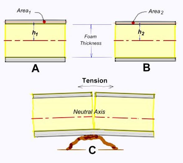
While touching on use of carbon fiber skins, I consider it important to acknowledge that due to their use, the associated Moment of Inertia is slightly lowered (assuming the same core thickness), so working directly with only material strength can be misleading. This sketch will explain this point by comparing A with B.
Putting some numbers to an example will help, so here we go.
Relative panel inertia can be compared based on an assumed strip of the laminate, as shown above. Its value is a combination of the inertia of the skins plus that of the core. Let’s assume a strip 50mm wide for both A and B.
We know that the inertia of the beam flanges is closely represented by the formula: 2 x Area x h^2 … with the ‘h’ value being the distance from the center of the flange area, to the Neutral Axis.
While the core thickness will be identical in both cases, the ‘h’ value will not only diminish by HALF the change in skin thickness, but the actual area will also diminish by the direct change in skin thickness. And the lowered ‘h’ value is ‘squared’ too, thereby increasing its effect.
So assuming a core of 10mm with 2mm shell, for case A, h1 = 5+1, giving Inertia for A as 2 x (50x2) x 62 = 7200mm4
For case B, if the CF skin is only 60% thickness compared to the glass, the thickness will 1.2mm and h2 = 5 + 0.6
This gives a flange inertia for B of 2 x Area x h^2 = 2 x (50x1.2) x 5.62 = 3763mm4 which is only 52% of A !!
To be fair, we need to add in the Inertia of the core which will be the same for both A & B, and as its of foam, its effective Inertia will likely not exceed 20% of the flange value, so taking 1440mm4 will be conservative. By adding this to both values, it reduces the difference between them (7200+1440 vs. 3763+1440), but still only 60% of A !
Regardless of whether the figures represent an exact case or not, the above example shows how quickly the Inertia drops with a small decrease in skin thickness. As BM / Inertia = Stress / y (and y = distance from NA to outer fiber) the stress is inversely proportional to the Inertia. So a 40% drop in Inertia means a 40% rise in Stress.
Now some carbon fiber can certainly take 40% more stress than Fiberglass, but this reduced Mt. of I should not be ignored and should be remembered in your choice of what CF cloth weights to use.
I would then also argue that it becomes more important to use at least two layers of different weave, rather than one thicker one, as the more rigid CF skin will otherwise still be more prone to punctures.
So, taking the above factors into account, using 70-75% of the glass weight would better match my personal recommendation when substituting carbon fiber.
The exterior at the bottom will also need a thicker skin to resist damage from grounding and one option is to incorporate a light but tough Kevlar cloth under a surface cloth of glass as it can be very effective, but it’s important that Kevlar is kept well sealed as it does tend to wick water. It’s also important with cored panels that the Neutral Axis is not brought down too low by skins of a great difference, or the thinner inner skin can then become overloaded in tension. (see ‘C’ in sketch above), But as all fibers are stronger in tension than in compression, its normal to have a thicker skin on the outside of a hull shell.
Bulkheads can generally use the same core as for the main hull, but decks that will often be loaded with locally high knee and heel loads will generally need a thicker denser core, along with thicker skins both above and under. The upper skin is for the local knee loads, but the lower one is for the tension face carrying the full body load between the beam spans.
While having a good deck camber can substantially add to its stiffness, I am personally only in favor of this in areas where one does not need to stand and work, as it’s just too easy to slip off. Flat or near flat decks are far more relaxing to work on, especially as one gets older, and they can easily be arranged to drain fore & aft off the main hull, while the ama decks can (and should) be sloped about 10 deg. down on their inboard edge, so that the ama becomes level (and more vertical) when a trimaran heels 10 degrees ... a common sailing angle.
While the above should give the builder guidance for the choice of a core and basic skins, suggested joint details for a hard chine hull will be covered in a follow up article, as well as ways to create the panels needed. Another article will give some guidance in selecting a safe allowable stress for carbon fiber laminations.... as required to resist either compression or tension.
Mike 2025
Read more Construction Tips & Techniques.
"New articles, comments and references will be added periodically as new questions are answered and other info comes in relative to this subject, so you're invited to revisit and participate." —webmaster
"See the Copyright Information & Legal Disclaimer page for copyright info and use of ANY part of this text or article"