


Compound Curves
Unless it's a barge, scow, or Jonboat you're building, boats are generally formed with curves in plan view—such as for the deck and waterline. If you then desire to combine that with a curved midship section (the section you'd see if you cut across the boat in the middle), then you are heading into the fascinating world of compound curvature.
A strictly planing hull (as often preferred for a motorboat) can avoid that rounded midship section and therefore find ways to avoid compound curvature.
(That does not mean that their sections will all have straight lines as they can use what is known as hydroconic development to achieve a good shape. To quickly understand this, just stand a conical paper cup upside down. You know you can make that cup with a piece of flat paper. But if you now imagine a slice taken across the cone at virtually any angle, that shape will not be straight but curved in a more elliptical fashion. So if we now lay the cone on its side and imagine the bow of a boat starting a short distance down from the apex point, we can now visualize the forebody of say a motorboat shape, that although having rounded cross sections, is still capable of being made from a flat sheet rolled around the surface of that cone. One of the straight lines down the cone, will likely run close to where the waterline will be).
But boats that need to travel efficiently at slow speeds, such as a yacht that is wind driven, will have less resistance overall in the lower speed range, if its sections are rounded. (Reviewing the 2017 article on Simple Design shapes should further help to understand this. See http://www.smalltridesign.com/published-articles.html)
This creates the need to build Compound Curvature and there are many ways to achieve it. One popular method is to use very small planks or strips, placing each at a slightly different angle as you cover the whole hull. The advantage of small strips is that almost any shape can be readily created. (see Construction Methods on this website)
Another is to 'stretch' metal by compressing it locally, so that it 'swells out' to create a rounded bilge (hammering is just one way). Another is to spray chopped strands of glass into a mold with resin to bind them, or to lay in various fiberglass cloths that can each be easily shaped to the desired form, and then wetting them with resin and allowing them to cure into shape.
Another is to have two molds that almost exactly fit inside each other except for a thin clearance space that will define the shell thickness. Then, by melting plastic powders in that space and rocking them around, a thin shell is formed that takes on the mold shape, and rounded polyethylene canoes and kayaks are built like that (commonly called 'roto-molding').
Yet the easiest and fairest way to build a boat is by using large flat sheets, as when curved, these tend to be fair by their very nature. But then the question comes up, just how CAN we get around this need for Compound Curvature?
Well, many designers have puzzled over this question and some have found some interesting answers. Let's look at some of them and perhaps you'll be inspired to create a new one for yourself!
One could say that designs with multiple chines or lapstrake*, can actually achieve some compound curvature. Overall they have, but there are many seams and in most cases just too many small knuckles to display that totally rounded appearance. The cold-molded method* of using many flat veneer (or plywood) strips can produce compound curvature, but there's a lot of fairing to be done, as again, each strip will initially join with a very small knuckle.
An interesting development of cold molding, was Jim Brown's idea to create large panels within (or over) a mold that already had some slight compound curvature built into it. Once molded, he'd then join them together and so created his Constant Camber system*.
Other systems also exist that slightly twist or torture the plywood to get the compound curve they are looking for. If the curve in plan view is very low, then it's easier to get a slight Compound Curvature, so long slim hulls DO make it easier. Because of this, the hulls of the 20' Olympic Tornado Catamaran can be made with tortured ply* and so can other multihulls, with the proviso that they have no reverse curves. Some small plywood dinghies have induced compound shape into their bows by cutting multiple splits into the forefoot and then backing the area with another thin plywood before filling and fairing. The 'Cherub' was one such design.
Some designers use a simple mold to build up a plywood boat side with the bilge-curve as required for the midship-section already built in, and then use a little torturing and profile trimming to get the hull to fit together at the bow and stern. The Cylinder Molding system* uses this concept and as successful as it can be, it is limited to narrow hulls.
Two other concepts, although very different in their materials and construction methods, have something in common. They both handle the double curvature at the bilge by cutting the panel material into small strips that permit each to take a different position compared to the main wrap-around skin that goes from bow to stern. Just look at this sketch and you'll see the idea and their similarity.

The Radius Bilge system* that I've attributed to Dudley Dix (see here) was in fact in use for steel hulls for many years and is still sometimes used in that way. But Dudley took this a step farther and successfully built himself a 38' monohull in plywood using the same approach. Choosing to try this with a monohull first was quite a major plunge as such boats have more compound curvature than a multihull. But the boat proved solid enough to sail over 20,000 sea miles and cross the Atlantic 4 times, so it's hard to argue with its strength! Once faired off and painted, the boat would pass as a fiberglass one, so it also succeeded as far as compound curvature was concerned. More recently, DD has designed a catamaran with this concept and with its long straight hulls, the concept must work even better.
The other system on the sketch, is one developed from scratch by multihull designer Derek Kelsall, now of New Zealand that he calls the Kelsall Swiftbuild Sandwich or KSS*. Derek is an experienced ex-UK designer, builder and sailor with some record-breaking boats to his credit. See Interview with Derek Kelsall
Kelsall's KSS System
Derek's system is so different and unique, that not all designers and builders have accepted it's interesting features. First of all, it's not made with plywood but with a fiberglass sandwich laminate. Secondly, it's not built on a form or shaped mold, but laminated on a flat table. Thirdly, it successfully uses polyester instead of epoxy, with important cost savings. The list goes on. Fourthly, it uses both vacuum-bagging and something relatively new for amateur builders—'resin infusion'. This permits the smelly job of resin application to be done 'under cover' and in some States, that's the only way some professional boat builders can meet the increasingly stringent environmental laws re air pollution. (Read more about this in the article on Vacuum-Bagging and Resin-Infusion.)
The KSS system uses two very simple jigs for pulling the lower edge of the large side panel around the bilge area into a boat shape and once there, additional fiberglass reinforcements are added as needed in the conventional hand-layup manner.
From the sketch (that just crudely shows only part of one full-length panel) one can see that the upper part of the 'fingers' equates to Dudley Dix's bilge panels—but in the case of KSS, these continue right across the bottom.
Above the finger cuts, the panel is laminated with a foam core and FG skins on both sides— including a surface gel coat too. In way of the fingers, there is initially only one layer of glass (unidirectional & parallel to the cuts) so little strength is lost by the cuts. Once the fingers have been curved into shape across the bottom and joined with the mating panel at the centerline, then additional layers of longitudinal unidirectional cloth are added to the bottom and bilge, in order to provide the strength matrix required.
It does work, as Derek has overseen over 40 of his designs built to this system but there will be more bottom fairing than on most other systems. However, for a long, slim catamaran hull this is not generally a large surface and anyway, this depends on the finish and fairness you require and some may not be so critical of surfaces below the waterline as others. The more parallel are the sides, the less slits will be required, but the reverse is true for wider hulls, so using this for a monohull would not work well, and any significant reverse flare would appear difficult if not impossible.
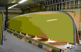
But for a typical slim catamaran, the topsides are nice and fair (see below) and look very professional and first class—coming straight off a finely surfaced table mold. In addition, the KSS system also combines a unique 'deck edge radius' (DER) molding on both the topside and the deck laminations and these fit one-over-the-other, to make a strong and attractive deck edge.
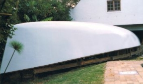
Here are photos of the finished hulls from these last two systems, showing that decent (non-complex) compound curvature can be achieved from flat sheets with some creativity and fairing.
*Read more about ALL these construction methods in the section on Construction Issues see: Construction Methods Index and Radiused Chine
"New articles, comments and references will be added periodically as new questions are answered and other info comes in relative to this subject, so you're invited to revisit and participate." —webmaster
"See the Copyright Information & Legal Disclaimer page for copyright info and use of ANY part of this text or article"