


Home Built Test Rig
Having had a few enthusiasts interested in a simple test rig, I thought I would explain my own little set-up and the basics behind it.
Accuracy is one question that often comes up. My thinking and experience to date on this is that 'it's not really that critical'. I am pretty confident that my measurements are within ±20% of what a multi-thousand dollar machine might register and perhaps closer.
While I admit that is quite a difference, one needs to keep in mind that, even from a very sophisticated test machine, the variation of results from what appears to be identical samples (that include wood), is often in the range of ±30%!
 Two other factors should also be considered. One is that we need to apply a safety factor of at least 2.5 with wood or wood/composite structures (due to high variations in grain strength and other unknowns) and finally, that any tests conducted are perhaps of greater value in COMPARING woods and joints—and for that, the relative accuracy is probably more in the order of ±10%. Quite good enough for most design work.
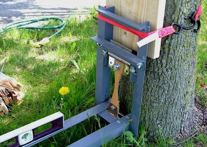
The test rig works on relative leverage. If a weight is placed at the end of a relatively long lever, a fairly high force can result at a distance much closer to the pivot. What is important is that the loaded arm has some means of adjustment so that it can be placed close to horizontal, relative to a vertical placement of the sample being tested. Otherwise the relative leverage might change too much and accuracy would be further affected. So use a level—as pic above.
Just to clarify, the sample to be tested is bolted top and bottom to the center of the flange of a heavy hinge. The free hinge flanges are bolted to the transverse angle frames, one adjustable one across the top, and the other is one fixed to the lower horizontal rack that will carry the variable test weight .. 34mm horizontally out from the lower hinge pin on my rig. That short horizontal distance is very important to record accurately, whatever it is on your rig .... as it will define the ratio of load to test force. The greater that small distance the higher the accuracy, but you will be more limited in what strength you can test. I would definitely not go less than 30mm though, or accuracy will suffer too much. You can always 'weaken' your test samples to suit the capacity of the Rig by 'waisting down' each sample. .. but there again, if made too small, consistency and accuracy will suffer again. What I choose was a practical compromise for my needs.
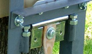 For this rig to offer built-in adjustment, the top sample-retaining-bar can be raised or lowered to place the lever arm horizontal. This is achieved by slotting the holes in the top cross beam (angle-bar), and taking the load on sturdy, adjustable bolt heads (see pic left). For high loads, the lever arm will need to start above the horizontal, so that it is close to horizontal when the sample reaches maximum load. A little trial-and-error is involved here.
The weight is varied by simply adding water to a container and then measuring its weight on a calibrated bathroom scale, after the sample has failed. Assuming the structure of the test rig is strong enough, one can increase the applied load in steps, by adding 1 or 2 steel plates of say ¼" (6 mm) thick under the water container–and then including that as part of the documented test load. In my case, I can go to a maximum of 52 lbs of water, plus 3 plates of 11 lbs (5 kg) each, giving 85 lbs (38.6 kg) total maximum. If preferred, one could also place a bathroom scale under the test load—water container etc—as a live but crude 'load cell'.

Strapping the frame to a sturdy tree works well to carry out tests and it's suggested to place a block under the loaded end, allowing 2" clearance, in order to catch the load when the sample fails.
The leverage of this weight compared to the attachment point of the test sample from the pivot point, gives a potential maximum test load of 1000 ÷ 34 × 85 = 2500 lbs (~1136 kg). As this is still not very much, one needs to be creative and design test samples that are relatively small or perhaps represent only a small part of the real thing. Actual strength of larger pieces can then be estimated by 'justifiable engineered extrapolation'.
This particular rig uses a short 3⁄8" (9.5 mm) diameter bolt to attach the test sample, top and bottom. Sometimes this means that the ends of the test piece needs extra reinforcement to prevent a shear out of the test material. Bi-directional fibreglass on both sides will generally achieve this but the user will need to experiment and be creative for mounting. The nominal distance between the 3/8" dia mounting holes is 6.5" (165 mm) on my rig.
It's also possible to test compression strength of small 50 mm long samples, by placing them on the lowest angle bar of the vertical part, and permitting the horizontal angle on the hinged part to load down on their upper ends. It's a little fiddly I admit, but can give one some useful relative figures at least. Again, the ratio of lever arms is what determines the load at failure.
Test samples will need reinforcing where bolted on, to be sure the failure is in a controlled location where it is cut to form 'a waist'. That 'failure location' needs to be assessed and measured accurately, as that is the X-section that will directly relate to the load at failure. Theoretically, the weight of the lower arm should be added to the Weight Added ... though as its relatively minor, you may choose to forget this and reason that it adds a small margin to your figures.
So here (above) are dimensions of my rig and enthusiasts are invited to use the info and built their own—be it larger or smaller. I just hope you take care to set things up square to get reasonably valid test figures and then share your results.
Some of the test results given in this article on Hardware Mounting, came from this test-rig ;)
Have fun!
Mike
Proposed scantlings…

If you go bigger with such a rig, scantlings will need modifying and so will the manner of clamping samples. Right now, it works at its limit as designed.
"New articles, comments and references will be added periodically as new questions are answered and other info comes in relative to this subject, so you're invited to revisit and participate." —webmaster
"See the Copyright Information & Legal Disclaimer page for copyright info and use of ANY part of this text or article"